Wednesday, 2nd of July
This is nms-online-zln
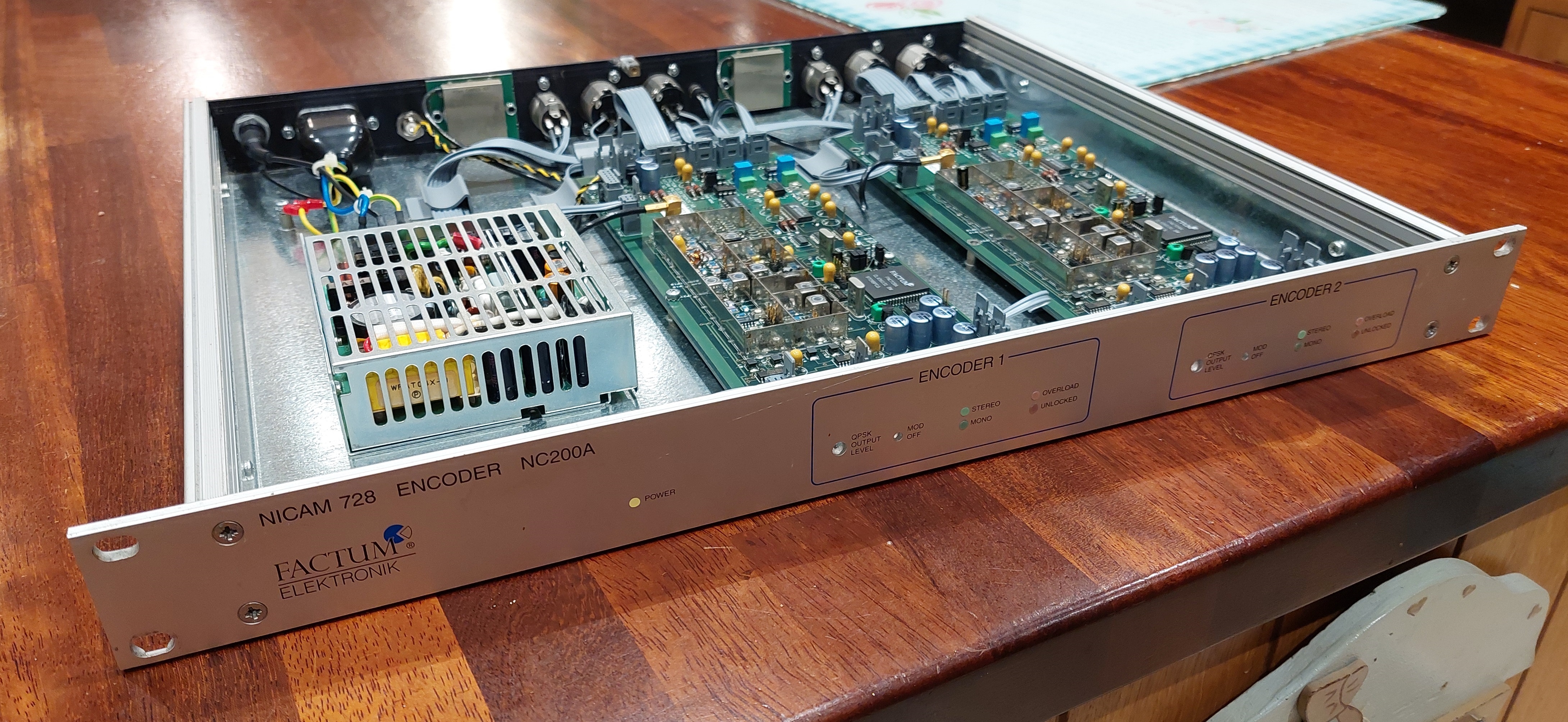
I purchased this Factum Electronik dual NICAM 728 encoder from eBay in a "not working" state - this, I assumed, was due to the seller being unable to test it (the description stated it was from his late father's workshop), and in any case it was the cheapest unit of it's type I've ever come across; As such I placed a single, winning bid of £50.
Upon powering up the encoder for the first time, a few issues became immediately obvious: First, the "Unlocked" warning LEDs lit solid and didn't disappear for several minutes - and secondly, the complete absence of any output; neither the IF nor Mono outputs carried any signal.
I therefore decided to dismantle the thing and observe it's operations. I discovered a number of interesting things, not least that there's a digital output on the board; applying an oscilloscope to this revealed a sensible looking digital waveform and clock, so at least the digital portion seemed to be working.
Upon further inspection, it became apparent what the issue was: the boards expect three power rails, +15v, +5v and -15v; however the +15v supply was AWOL. Now, the question was, is this a power supply issue or a board issue? It quickly turned out to be a board issue, as disconnecting one of them allowed the other to begin working.
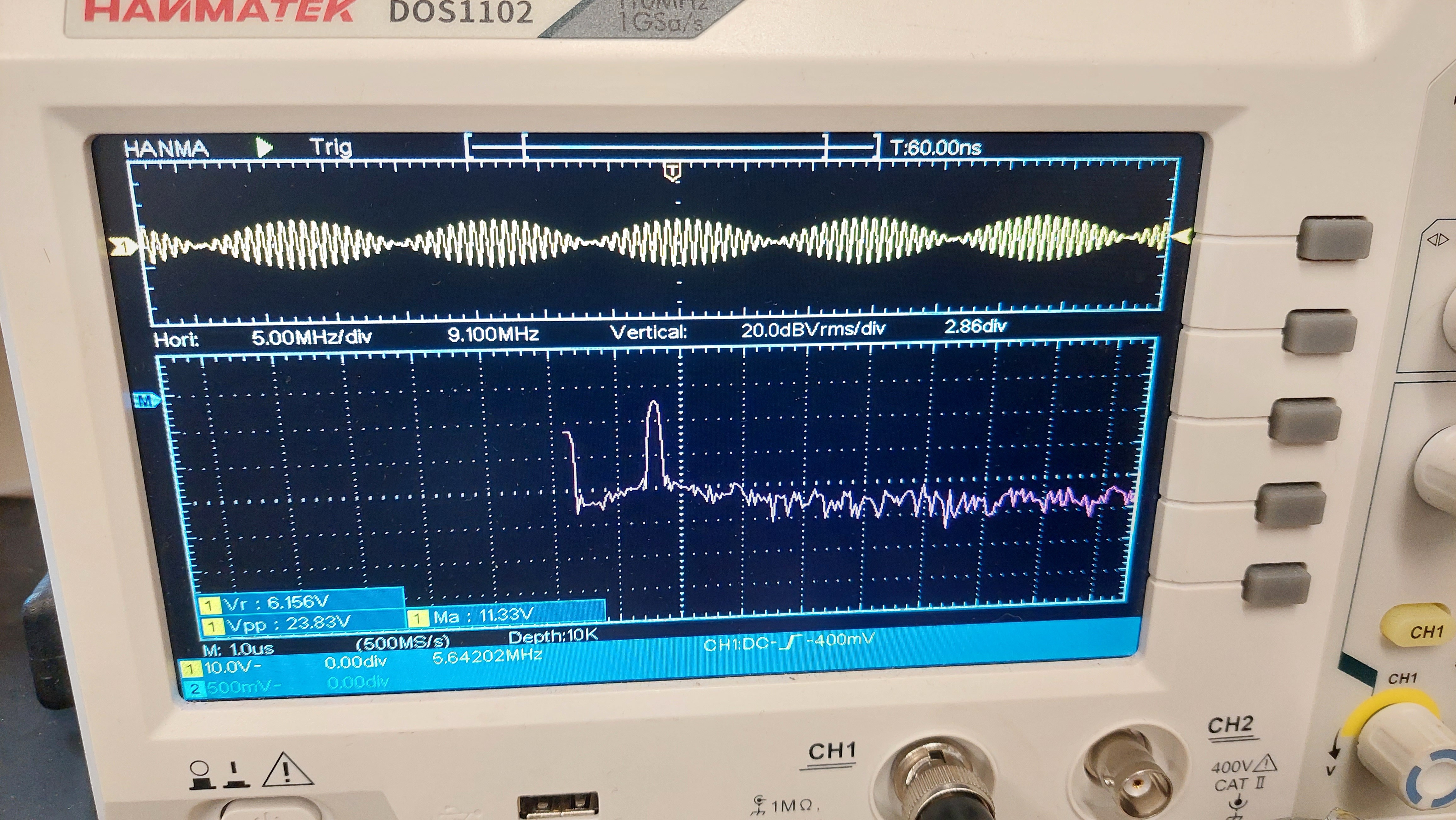
Well, a bit. While it now emitted both a mono mix and an IF signal, the IF signal did not look anything like what I would have expected a NICAM 728 QPSK waveform to resemble; For a start it didn't appear to correspond in any way to the raw digital output waveforms, and far from any phase-shifts being visible it looked heavily amplitude-modulated; but we shall return to this a bit later.
The other board displayed a dead short between the +15v rail and ground. In order to trace this down, I took the rather reckless and completely inadvisable step of connecting it to a bench power supply and applying 15v at a significant current. The idea was that this would heat the faulty component and make it easier to find - which it did, in fact, as I discovered a burning inductor under the RF shield.
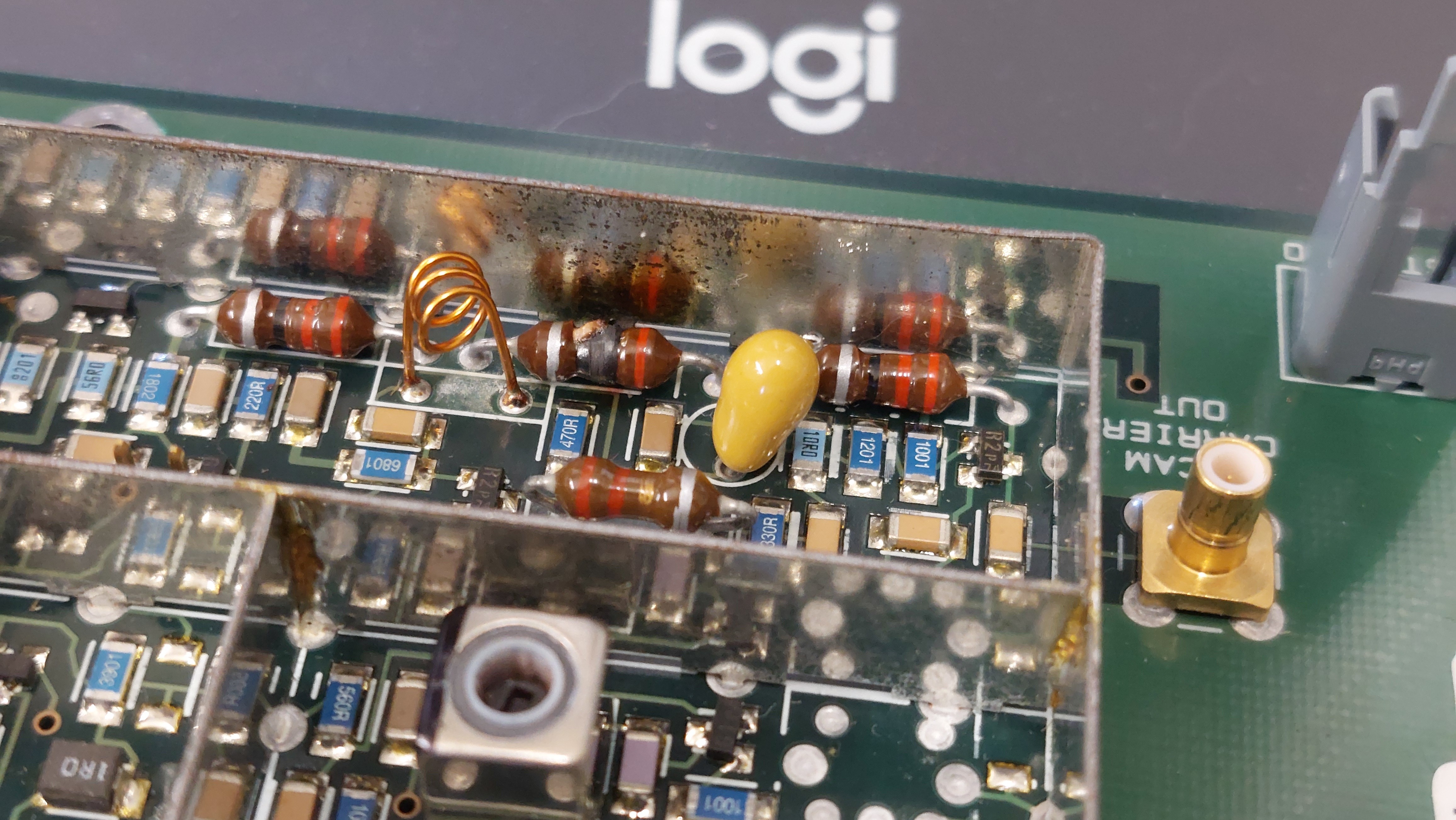
The inductor in question was a 1 ohm variety connected in series between the rail and two parallel capacitors, a 10uF tantalum and an anonymous SMD ceramic. Removing the tantalum revealed it had indeed failed to a dead short, therefore I replaced it temporarily with a 10uF electrolytic.
Despite some obvious heat damage to the inductor, re-powering the unit revealed a sensible looking IF output; It still appeared more amplitude-modulated than I had expected, but nonetheless it corresponded to the digital outputs appropriately.
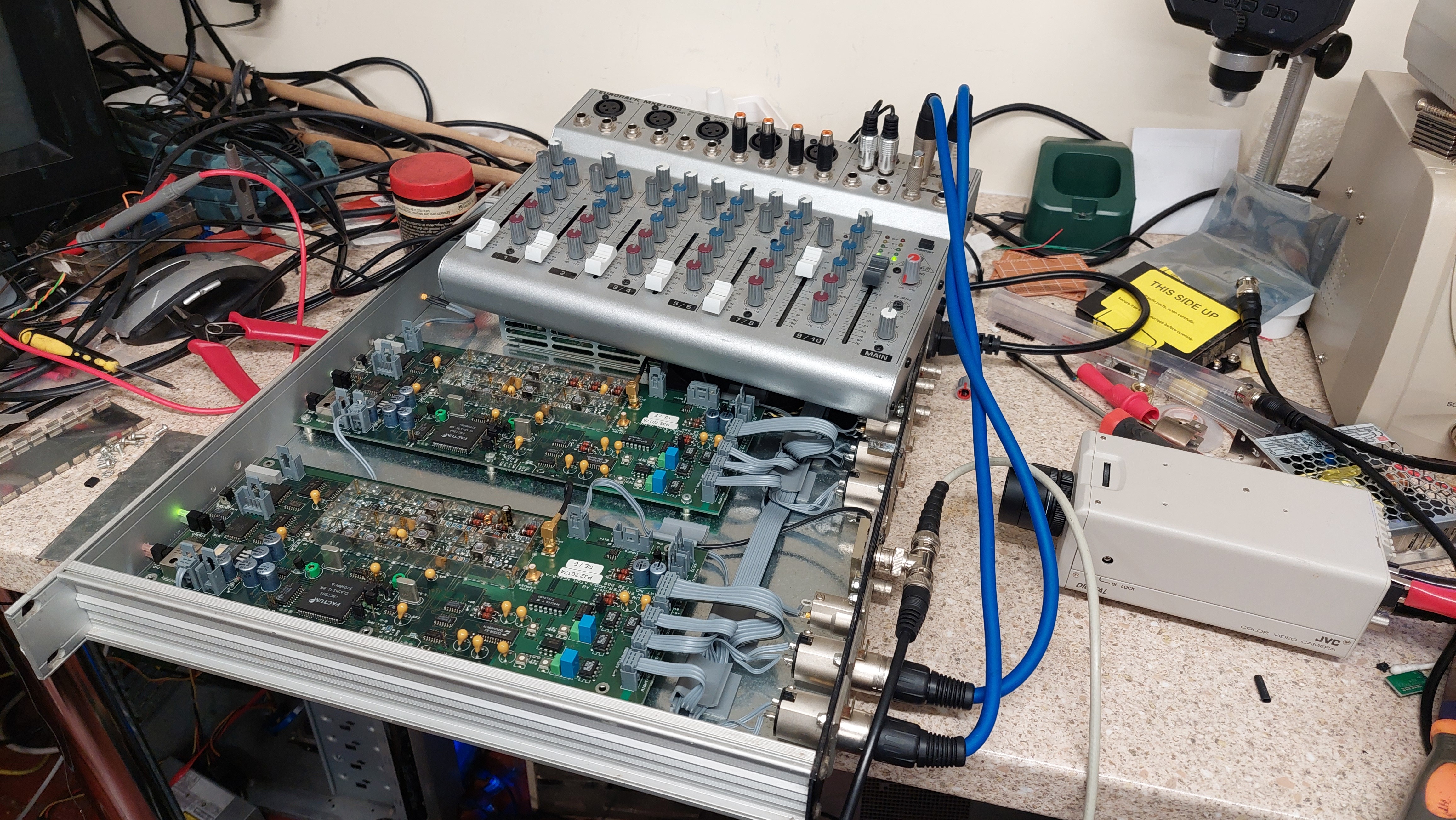
So, how does one test a NICAM encoder? Well ideally one would possess a dedicated decoder which could simply be driven directly from the IF output; However, I do not own a dedicated NICAM decoder (yet...), so this signal would need to be modulated onto an appropriate TV channel and applied to a suitably equipped TV or VCR. I had some reservations about how exactly to do this; wouldn't the modulator require a dedicated IF sub-carrier input? However, a friend online noted that "in 128k ZX Spectrums, Sinclair/Amstrad fed the FM sound carrier into the RGB to PAL chip's luminance input pin" - so why therefore couldn't one feed a NICAM sub-carrier in alongside the baseband video?
I rigged up a cheap modulator and connected both a camera and the NICAM encoder to it's video input via a BNC T-joint. At this point it became apparent that the encoder was not expecting to be used in this manner, as it introduced a lot of ghosting into the video; despite this, pressing the "info" button on the TV's remote revealed the magic words: "NICAM Stereo"!
 <
<
With no patterning or noise apparent on the vision signal (aside from the aforementioned ghosting, which appeared even when the encoder wasn't powered and therefore can't be attributed to the sub-carrier), I did some more testing to verify everything worked as expected; Indeed, the Mono/Stereo input induced the TV to switch from Stereo to dual mono mode and lowering the IF output amplitude adjustment to its minimum still produced usable results - I'll set that amplitude properly with the aid of an SDR later.
With one board now fully working (and a replacement inductor and tantalum capacitor on order), I turned my attention back to the first one. Now at least I could compare readings from the working and non-working boards to seek out the fault.
The boards feature a fair number of test points; despite having very little idea what these were *supposed* to be doing, these proved very useful as points of reference between the two boards. The encoders seem to work by producing a 6.552MHz carrier, which is then modulated by the NICAM data stream. Both of these signals are brought out to test points, and on inspection it was revealed that the NICAM signal did not display any variation; It looked like a 182KHz square wave, which I realised is exactly one fourth of the NICAM bitrate, 728KBits/s - therefore I think it must be some kind of test signal, with four bits high followed by four bits low continuously.
Unfortunately, despite obtaining the unit's manual from Factum (and a quote for a new unit at the low price of only £4000), I couldn't find any details of such a mode or how to disable it; Therefore I must conclude that the chip is faulty. Perhaps in future I'll replace it with a Raspberry Pico, which should have more than enough puff to handle NICAM encoding. We'll see...
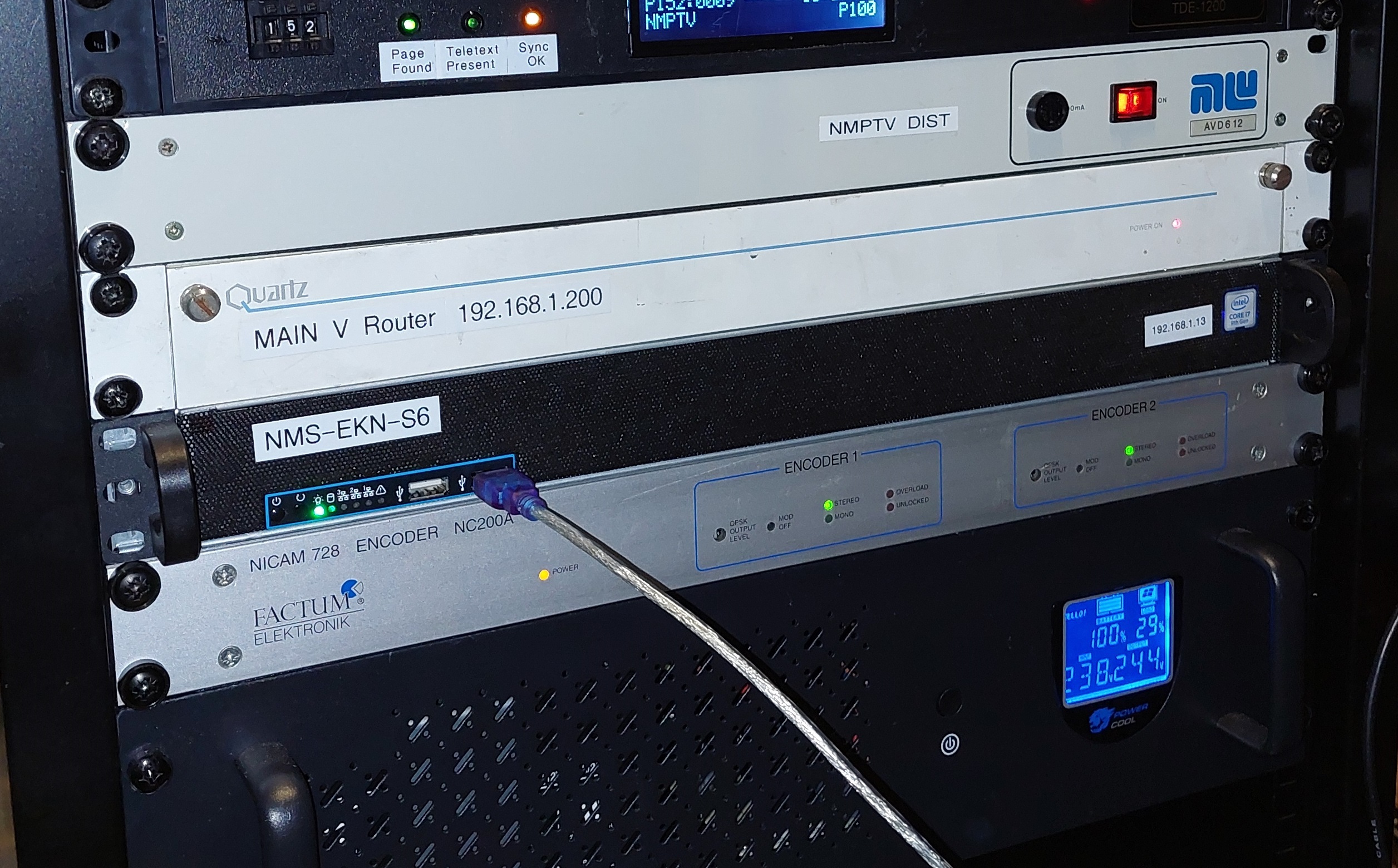
For now, here's what the unit looks like installed in the comms rack with all my other old kit. I think it looks brilliant, even though it isn't actually doing anything useful at the moment. In future maybe I'll pull it out and try getting Encoder 1 working too.