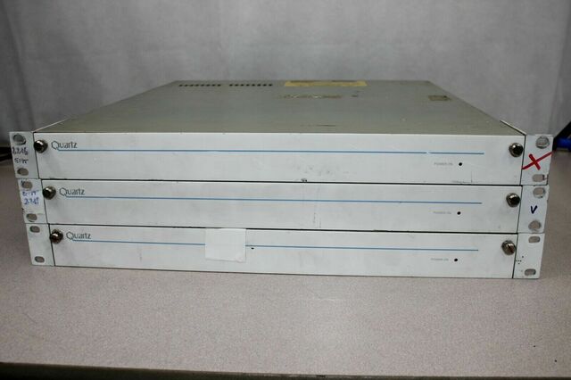
The three routers. I modified the centre one.
Saturday, 27th of July
This is thorium
The three routers. I modified the centre one.
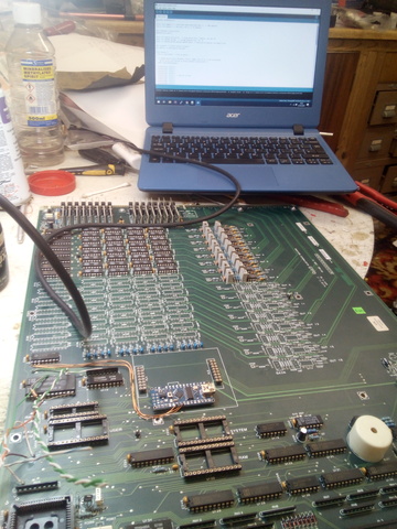
A few months ago, I came across three ex-BBC, rackmounted, composite video routers on eBay. According to the description, two of them worked, as in, powered up, but were otherwise untested. I put in a bid, mainly because I wanted the rackmount cases, and won them for £15 plus shipping. When they arrived it became obvious to me that while they apparently worked, they required a seperate control panel and I had no way of 'faking' the control signals to make them work. However, on taking one apart it was clear that it would be very easy to modify them for control with, say, an arduino microcontroller. I therefore set about reverse-engineering the circuit.
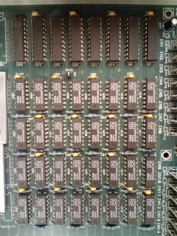
The router's video matrix
Testing the circuitry
The router uses a matrix of 32 GX434CD video multiplexer chips; four per output channel. Each multiplexer outputs one of four input video signals or can be 'disabled', that is it's output goes to a high-impedance state. Each output 'row' is controlled by a CD74HCT374E D-type flip-flop. All of the flip-flops are connected to a 'bus', which in turn is controlled by various decoder chips. To trigger whatever flip-flop is required, a 74HCT154 decoder is used; this takes a 4 line binary number input and turns off one of it's 16 outputs accordingly. It also has an output enable which can be used to drive all outputs to high.
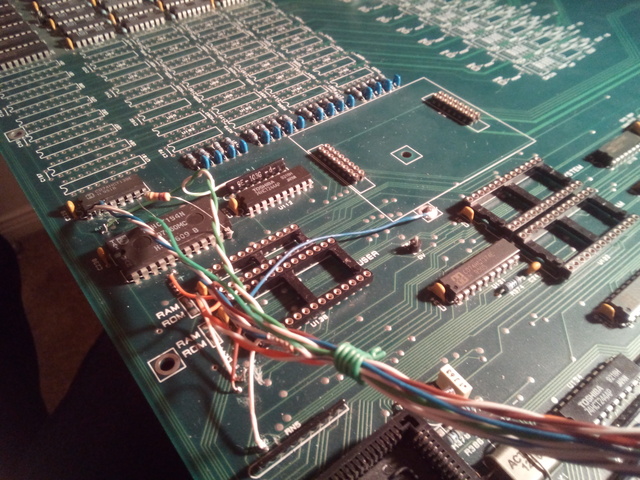
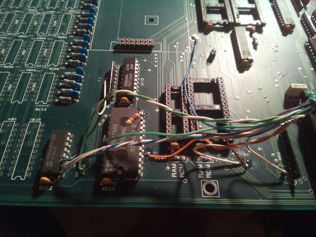
Reverse engineering the router
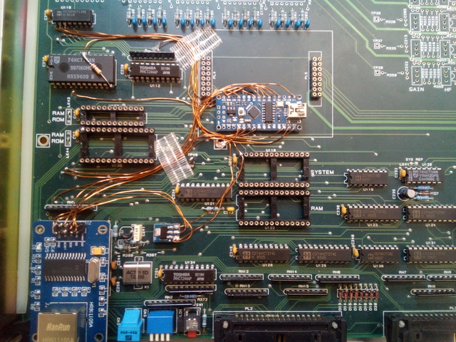
So, after much multimeter probing and datasheet reading, I figured out that I could do away with almost all of the existing control circuitry and control the video matrix directly with an Arduino Nano. I removed all the static RAM, ROM and microprocessor chips and set about controlling the system with my Arduino. Here is how it works: When you select a video source for a particular output, the Arduino has a 4 digit binary source and destination address. The most signifigent two bits of the source address go the CD74HCT139 decoder to select which of the four video multiplexers we want, while the two least signifigent bits go the the multiplexer to select which of it's four inputs we want. Meanwhile, the destination address goes to the 74HCT154 decoder to select which flip-flop we need to fire. After a brief pause to allow the outputs to stabilize, the Arduino pulls the 74HCT154's enable line, which in turn triggers the selected output's flip-flop, which sends the source selecion to the video multiplexers. The Arduino then relaxes the enable line and waits for the next command.
Building the Arduino into the router
To make the router more easy to control, I added an Ethernet card to the Arduino, allowing it to be controlled by a web interface. It gets the source and destination data from two hexadecimal digits in the URL. The Arduino itself hosts only a very simple web page which re-directs traffic to a dedicated internal page on my website. It uses javascript to send the correct source/destination to the router. Every time a route is made, the arduino saves the destination address to the source's EEPROM address. This means that it can read all the last set routings on boot up, so in the event of a power failure or similar the router will come back on exactly as it was previously. This also means that in future the router can tell you the current routings, but this is not implemented yet.
The finished system
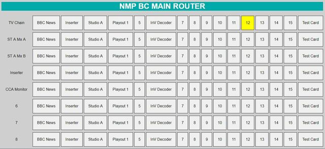
The web control panel
I want to have the web interface output the current routings, so that the control panel can illuminate the appropriate buttons.