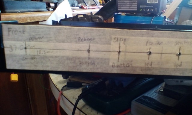
Front panel marked up and with the first pilot holes drilled.
Saturday, 5th of July
This is nms-online-zln
UPDATE 2020: Sadly this teletext inserter is no more. I was having problems with the VBIT-Pi and had the unit in my workshop for repairs. As it happens it was still there during a subsequent fire and has been destroyed. I intend to build another one in the future.
For as long as I've known about generating teletext directly on a Raspberry Pi, I've wanted to build a 'proper' teletext inserter, i.e. one that adds teletext to an existing video signal. Of the two ready-made projects I found online (VBIT-Pi and AVR-Teletext), AVR-Teletext seemed the easiest to recreate. I liked the simple circuit and all through-hole components. But I was discouraged from using it firstly by the lack of information and the 'dirty' signal it produced. Which left the VBIT-Pi with its scary surface mount components (I'd never soldered surface mount before). But after chatting to its creator Peter Kwan and watching some Youtube tutorials on SMD soldering, I was confident enough to give it a go. So I did. And the first one didn't work. But the second one did! The software was a bit awkward in comparison to the new VBIT2 but it worked. So it was time to build it all into a nice case. My main requirements were as follows:
So now here's some pictures of the build process.
Front panel marked up and with the first pilot holes drilled.
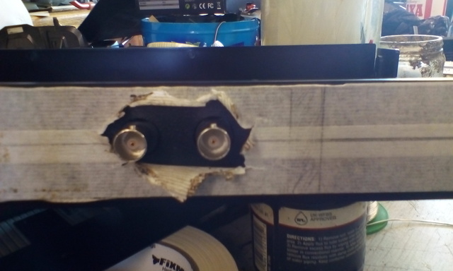
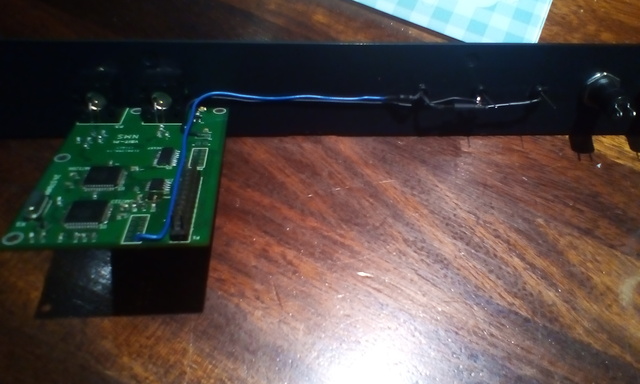
First test fit of the PCB with its sockets. Fits perfectly
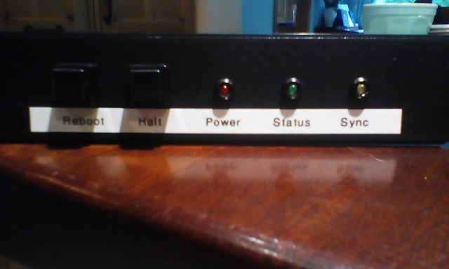
Front panel pretty much finished. What you can't see is the roll of label used getting this to look right... The 'Status' LED is connected to a GPIO pin. This is then set in
the /boot/config.txt file to mimic the Pi's ACT LED. If this LED is out, it's safe to shut down. The 'Sync' LED is controlled by the VBIT-Py software. It flashes with every
field of video. It may have been more accurately labled 'Inserting' as it it will only light up if there's a good video signal and the software is running. The 'Power' LED is
connected directly to the 5v power supply.
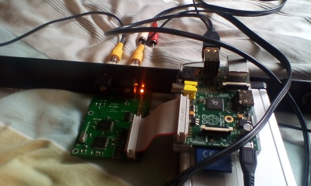
Testing the VBIT-Pi in the front panel (yes it's sitting on my bed!)
All LEDs are soldered to expansion sockets on the VBIT-Pi so I can swap out the Raspberry Pi if required. In future I recommend connecting components like this with sockets. I
ended up cutting and re-soldering these wires every time I needed to remove the VBIT-Pi, which is not only a pain but also left them looking rather untidy.
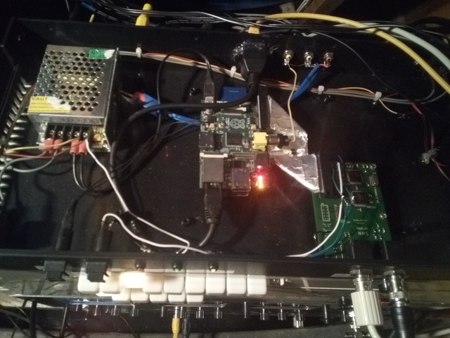
Looks a bit messy inside but it works OK. You can see the 5V power supply and the now unused rear AV sockets, along with the firmly glued Ethernet
socket! The only thing 'permanently' soldered to the Pi is the reboot button. I always had the thought that I might need to change the Pi eventually, so tried to leave it as
untouched as possible
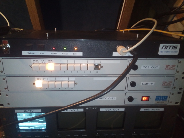
Finished product in my pile-of-stuff-that's-meant-to-be-rackmounted, proudly displaying my logo. If anyone's interested, it's printed on high gloss photo paper to match the
labels from my label printer. You might be able to make out the VBI on the bottom monitor
Update Nov 2019: Changed the encoder, decoder and regulator chips. This finally fixed the problem described in the 'DIY TV Studio' post, where the inserter could be very
unreliable with it's lid on. Turns out the problem was caused by a dry solder joint. Apparently I was rubbish at soldering at the time I built this. Some might say I still am.
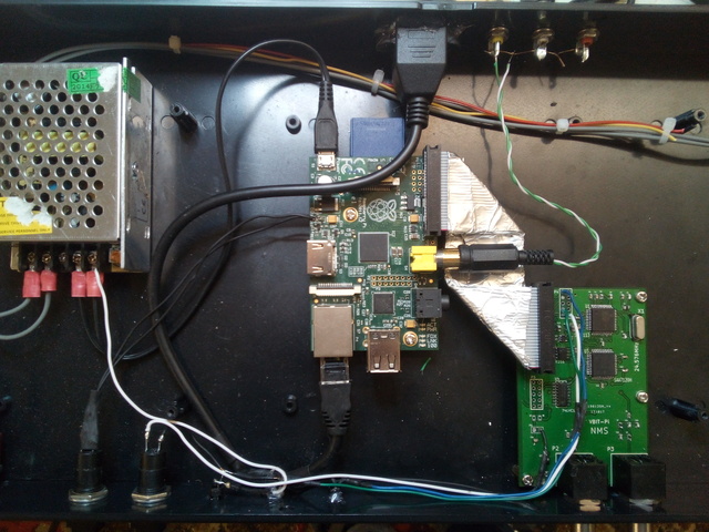
Also took the opportunity to clean up the insides a bit, removing the unused audio cable, fixing the video connector and putting some heatshrink on the front panel
connections. Also removed the noisy, useless and unrequired fans. This is the final result. Upcoming updates will probably be more software based, such as optimised boot
time (because 10 seconds isn't fast enough) and improved source switching.
The system uses VBIT-Py and VBIT2, but not in the way you might expect. The Raspberry Pi 1B seems quite unreliable under large loads, even when overclocked as much as I dare. So instead, the Inserter is fed by a seperate teletext server. The Inserter runs a terrible teletext packet client I wrote. What this does is receive teletext packets generated by VBIT2 and sent by this server program. It can switch between servers so that if one stops working there is no loss of service. My current version can also output a pre-recorded packet if no servers are available. It's not perfect, but has proved much more reliable than running the entire system on one Pi, which required multiple forced reboots a day, and also seems to be easier on it's SD card, which saves me taking it apart.
After I designed the VBIT-Pi 3, Peter Kwan very kindly wrote the VBIT-Py software to replace the old VBIT-Pi. This is much more flexible as it takes the data in from VBIT2 rather than generating it by itself. Also it works on versions of Raspbian other than Wheezy, which is a big plus.
The Inserter was great fun to build and even though its technically completely useless it gave me lots of experience with SMD soldering and inspired me to design what I thought was an improved version. While that isn't necessarily the case, it was still a good experience. If you've any comments, you can find contact details in the 'About' section of this website. I haven't wrote the code to allow direct comments yet. (upcoming project...?)