Controlling a Quartz Audio Router
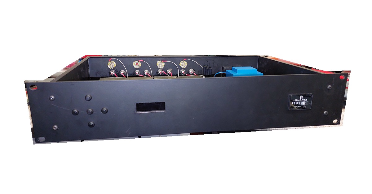
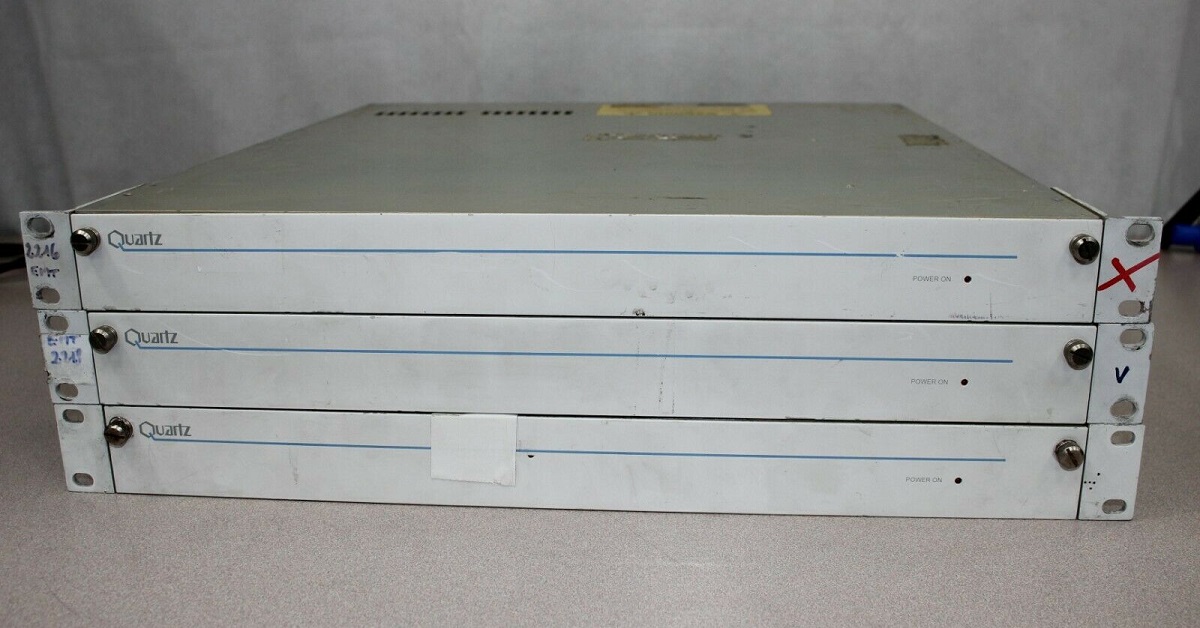
I bought this 32 in, 32 out router from eBay. I can't remember exactly where it came from, but safe to assume it came from some broadcaster or other.
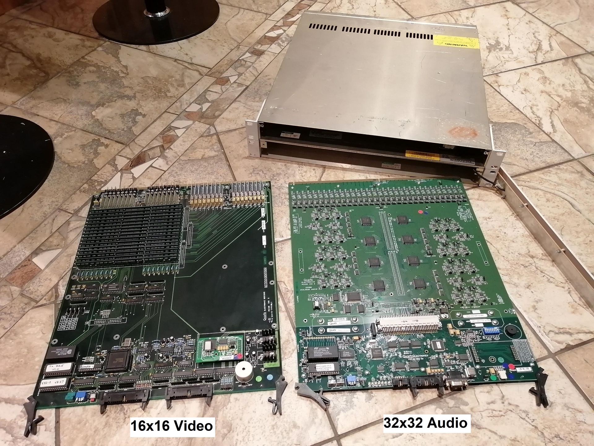
It's slightly newer than the video matrix I modified, but works on much the same principle, just scaled up a bit and aimed at balanced audio.
This specific model is designed for mono use - however it should be noted that the 16 by 16 stereo model is this exact same board, with maybe slightly different firmware - not that that will make much difference once I'm finished.
For those who don't know, a matrix like this is used to take a load of video, data or (as in this case) audio inputs, and connect them to any output. So instead of every piece of equipment being conected directly to each-other, they can each be connected to a matrix which can connect them together in any order required. They may also be used, for example, to take a load of outside lines and split them out to the required studios.
As before, these routers are designed to work together in a purpose-built Quartz system - and unfortunately you can't get the software for controlling or configuring these any more. The best you can manage is a standalone controller, which usually go for silly money, and may not even work without configuration anyway (I don't know, I have no intention of buying one to find out!).
My solution is, in the words of my friend Alistair, to "remove its brain and puppeteer the corpse"... ew, gross. In other words, I remove the matrix's microprocessor and associated circuitry, and install my own microcontroller - in this case, an Arduino Nano.
How It Works
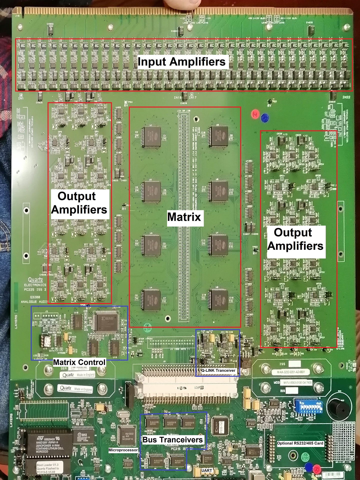
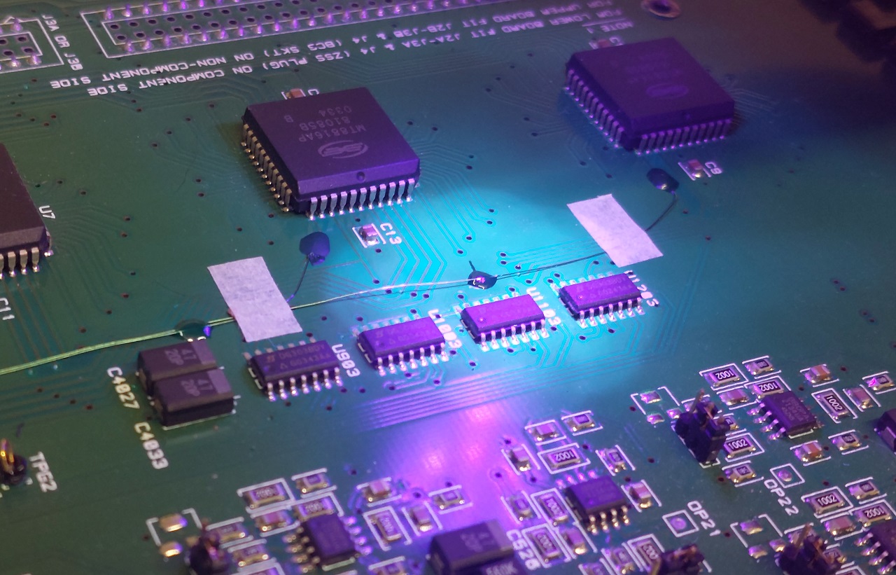
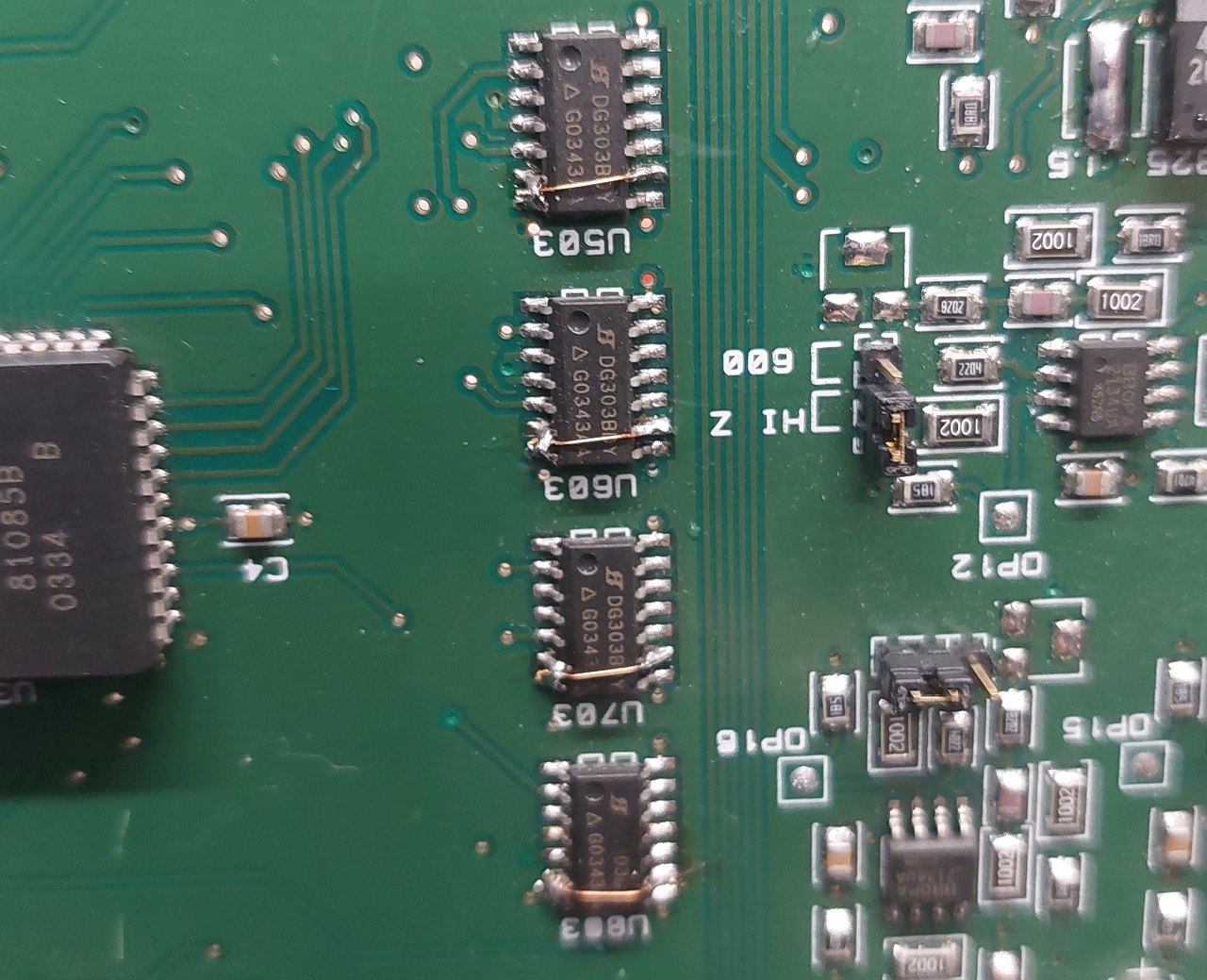
At the heart of the unit are eight MT8816AP 16 by 8 matrix switch ICs - these are actually bi-directional, but are configured in this instance to take 16 inputs and control 8 outputs.
The chips are controlled by a common address bus, data and clock (which they call "STROBE") - essentially each chip behaves as a 128x1 bit write-only RAM. Each chip is selected via a chip select line.
The chips are cleverly arranged to ensure that any of the 32 ouputs can receive any of the 32 inputs, with no spare or redundant channels.
Looking down at the PCB, each row of ICs is responsible for 8 of the outputs. The two columns are responible for 16 input channels each.
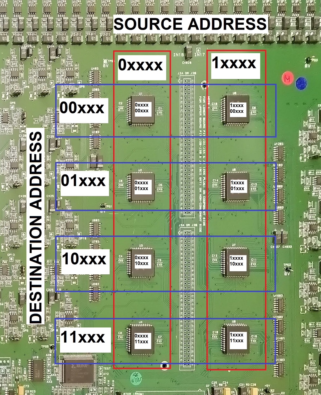
Looking first at the source - the address' MSB becomes the MSB of the chip select - so when it's lower than 16 the left-hand bank is selected, and when higher the right-hand is selected. The remaining four bits are sent to the IC's source address input.
The destinations are split between four ICs - therefore we use the first two MSBs from the destination register, they become the LSBs of the chip select. The remaining three bits go to the IC's destination address input.
With the appropriate IC, source and destination selected, the DATA bus is used to set the selected switch either on or off. Note that these matrices allow one to have more than one switch activated at a time - so when changing a route you must first un-route the previous link. When all is set correctly, the changes take effect with a rising pulse to the STROBE bus.
Modifications
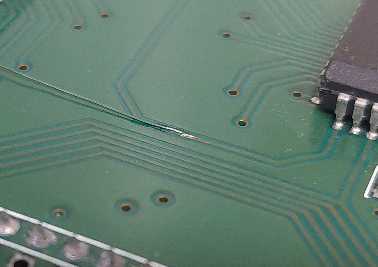
The first step was to actually put this theory to the test. I removed the FPGA (badly, see photo) and connected an Arduino to the data bus and one chip select. I also connected two inputs to my function generator, and used my oscilloscope to check the outputs.
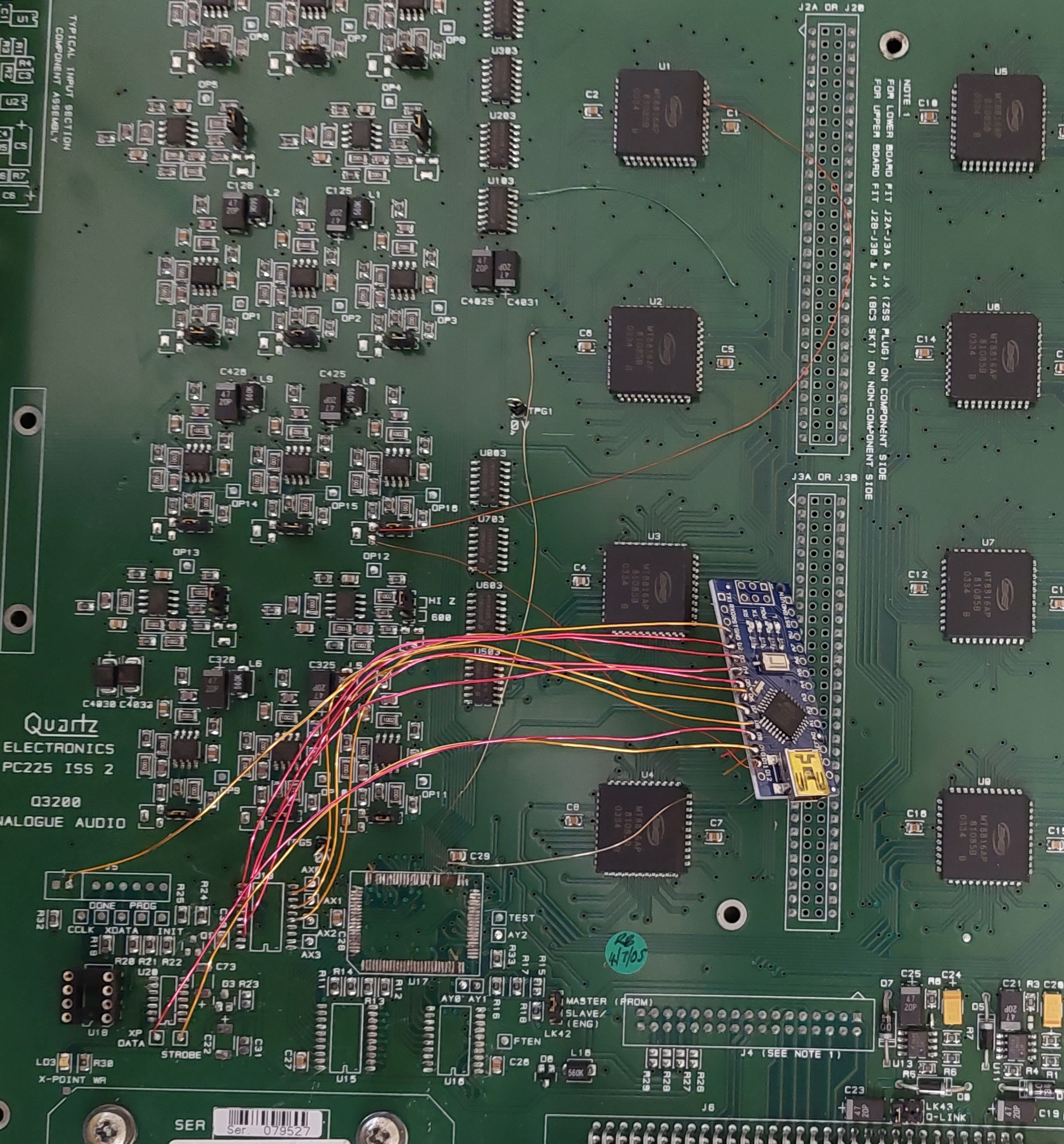
Almost all the connections I needed were handily brought out to test points, so I only needed bodge in the chip select and a reset line.
This test revealed that the addresses don't necessarily correspond to the actual input numbers. I mapped out the following look-up table for later reference:
{7,6,5,4,11,10,3,2,9,8,1,0,13,12,15,14}
However, the basic principle was correct and worked in spite of the unusual mappings.
Next, I used a 74HC238 3-to-8 line decoder to control each of the eight chip select lines.
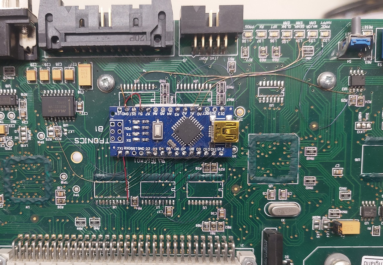
Unfortuantely the existing lines disappeared into an internal layer of the PCB, so I decided it was easier to just run bodge wires directly to each IC.
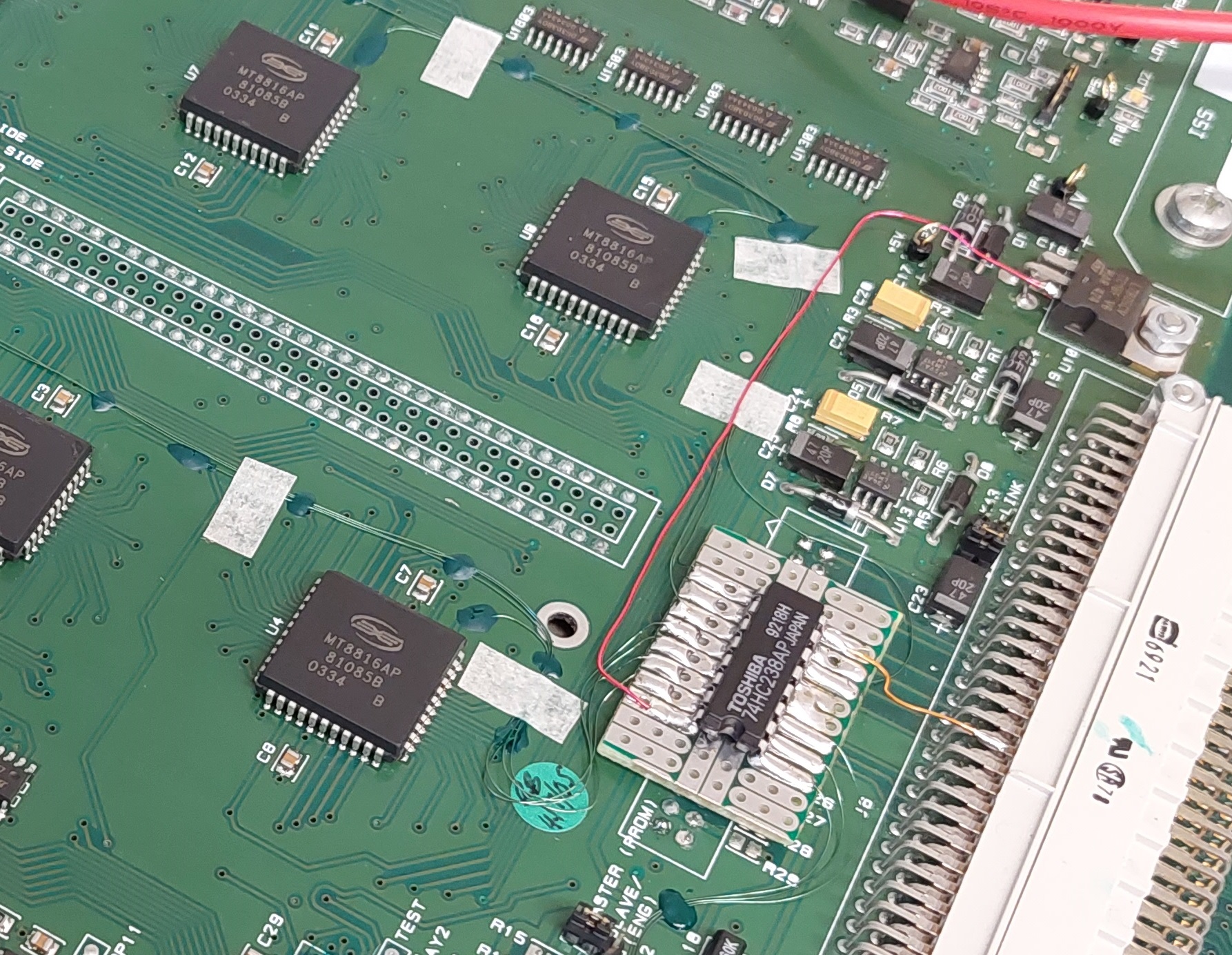
If you're thinking, "he's put the chip on the wrong side of the prototype board, what an idiot" - I did this deliberately so that I could get easy soldering access without having to remove all the lines and un-stick the board. Oh, and the connector underneath is for stacking matrices (in a 32x32 stereo, or 64x64 mono router for example) which I will never need - hence why I stuck this board on top.
For testing purposes I also soldered some sacrificial LEDs across the CS lines and wrote a piece of code to cycle through each IC to make sure everything was working as expected:
As you can see, everything appears to be working normally.
With the chip select working, it was now time to bridge the address bus back to the microcontroller. As I wanted to run these signals through the big connector that joins these two boards, I bridged these signals through the footprints of the bus transceivers. In hindsight it could have been useful to leave the transceivers in place, but they'd long been removed by this stage.
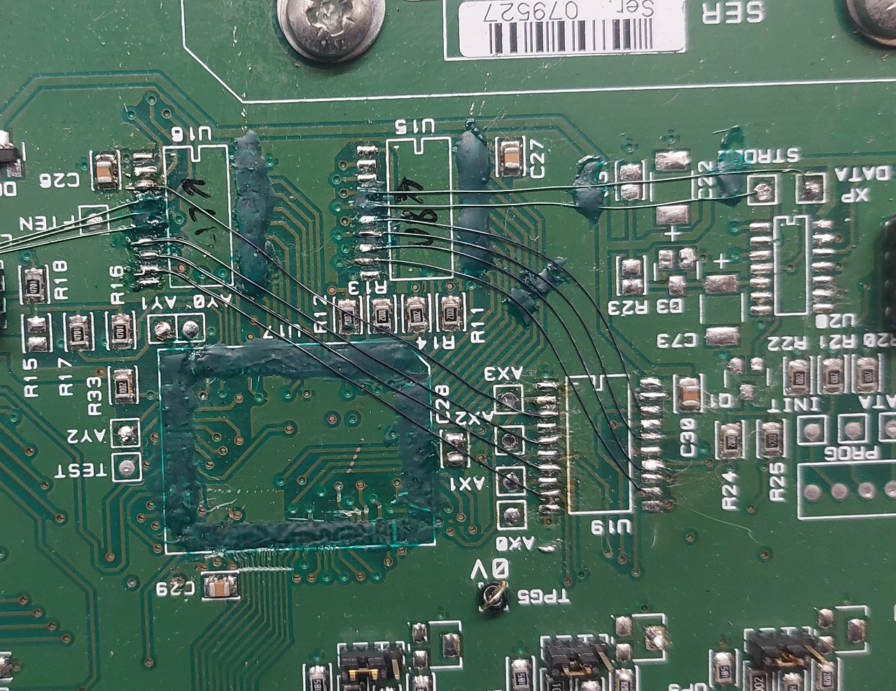
These traces end up on the controller board via another set of bus tranceiver footprints, ready to go into the microcontroller.
Last thing I needed to do was deal with these SPDT switches on the outputs. The idea of these is to switch between this card's inputs, or an external card in a stack. Since I'm pretty sure I'll never have a stack, I've tied all the control inputs to ground, forcing them to permanently switch to this card's inputs. Otherwise they have an annoying habit of flip-flopping on and off. Don't ask how I know.
Microcontroller
I considered using an ATMega328 soldered onto a bit of prototype board for this job, but ultimately decided to use the Arduino Nano I'd used for testing earlier - since it's essentially the same thing already on a board. I use it in a slightly unusual way though, as you'll see in a second.
I wanted to try and keep things fairly neat, so any chips I removed had unimportant pins covered by solder mask - as did the bodge wires. This kind of job will never look factory original though, short of manufacturing a custom PCB - and if you're going to that length, why not do it properly and build your own matrix with modern ICs? I also wanted to try and use some of the existing ICs, such as a Watchdog timer and UART, and the status LEDs.
The first snag I discovered was the Arduino bootloader makes the microcontroller boot too slowly - the watchdog timer would get stuck in an infinite reset loop as it timed out just shy of actually starting. So it must be flashed through the ISP header without any bootloader to avoid this issue. I connected both the watchdog's input and the onboard "Proc. happy" LED to the Arduino's pin 13. The pin must change state roughly twice a second, or the watchdog triggers a reset. This should avoid me ever needing to manually reset a frozen system (which is a problem with the video matrix).
I also hooked up the 'major' and 'general' error indicators. Not sure what major or general errors they will warn of yet but cross that bridge etc.
Serial Protocol
If you've read my previous article on modifying a video router, you may recall I built an ethernet module into it for remote control. However on this occasion I've decided to go the more traditional route of a serial interface. There are a number of reasons for this - it's more like the original interface for a start, and I think it gives more flexibility as I can connect it up to a PC or server for control at the moment, but possibly build a hardware controller in future.
My initial thought was for a super error-resistant system that would allow connecting multiple devices to an RS485 'bus' for control. However there were a number of problems with this - for one there'd be no way of manually controlling the matrix for testing (it involved Hamming error protection etc), and I realised that the chances of me ever needing to control so many devices it'd be worth doing this way were pretty slim.
So instead I decided to use the unit's existing RS232 port and UART IC and write a nice, simple command-line interface. This allows me to send it commands directly for testing, but will also be really easy to write code for in future for control from a web browser or whatever.
The interface takes a single, capital letter as the "command", followed by a space and then any required variables. So for example, the "Route" command looks like "R 'source' 'destination'".
There are, in fact, only 4 commands - which the matrix will helpfully list if you send it "H" (so I suppose that makes 5...):
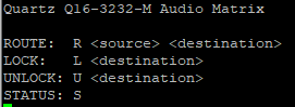
It's pretty obvious what these all do, but I'll run through them anyway. "Route" connects a source port to a destination port. "Lock" and "Unlock" mark (or unmark) a destination as "locked" to a particular source. It cannot be re-routed without first unlocking. "Status" returns a list to show what source is selected by each destination - and also if it's locked or not.
In hindsight, I should also have added a "Reset" command. All this needs to do is delay the loop for a second or so before the Watchdog IC will kick in and force a reset. I may add this in future if it becomes necessary.
All the routes are stored in the Arduino's EEPROM, so the system will always return to it's last state on a power cycle - including the lock status.
Final Stretch
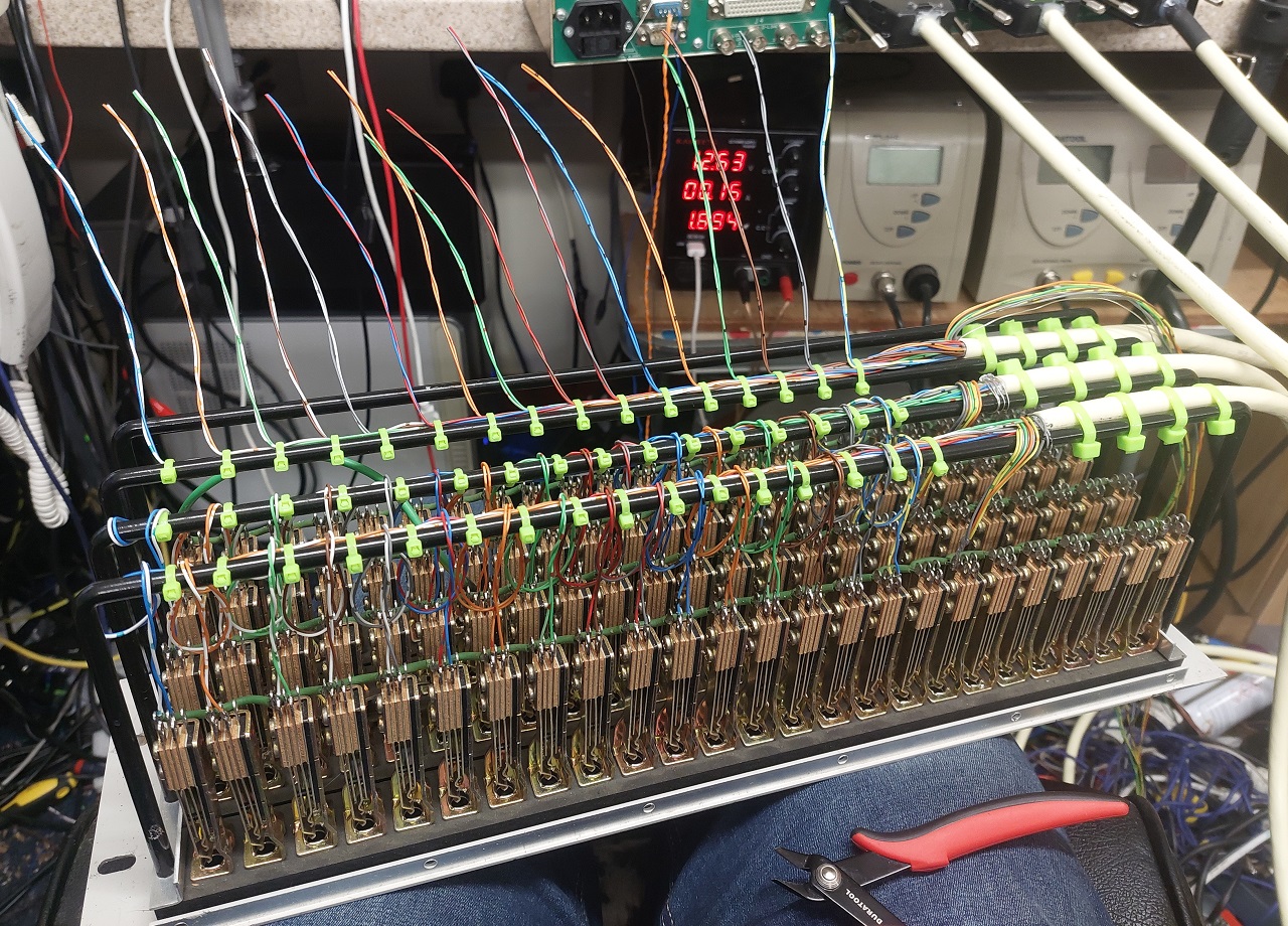
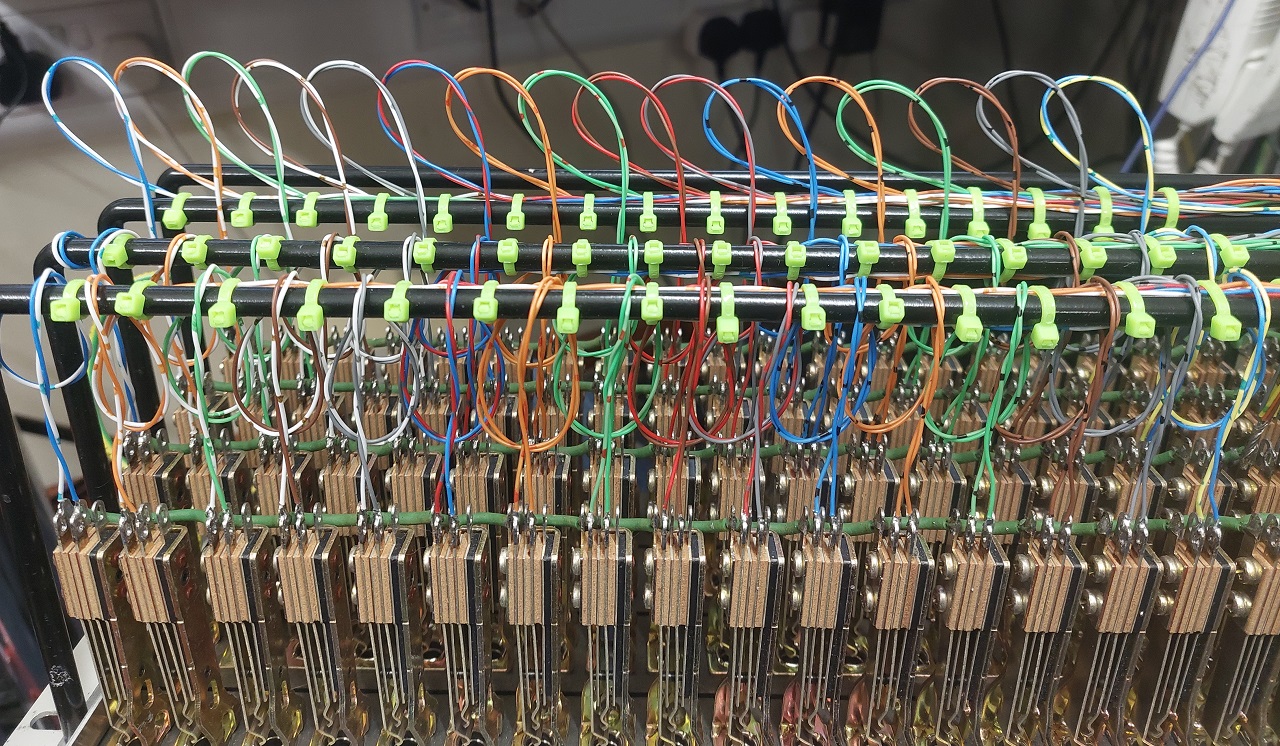
If you know nothing about broadcast equipment, you'd be forgiven for thinking the hard part's over now? Just plug in a load of audio devices? Wrong. To fit 64 balanced audio connections onto a 19" 1U unit, Quartz have used 4 massive 50 pin DSUB connectors. You're expected to connect these back to a patchbay or similar to break out the individual audio connections. So that just means I need to solder up over 256 individual joints. What fun!
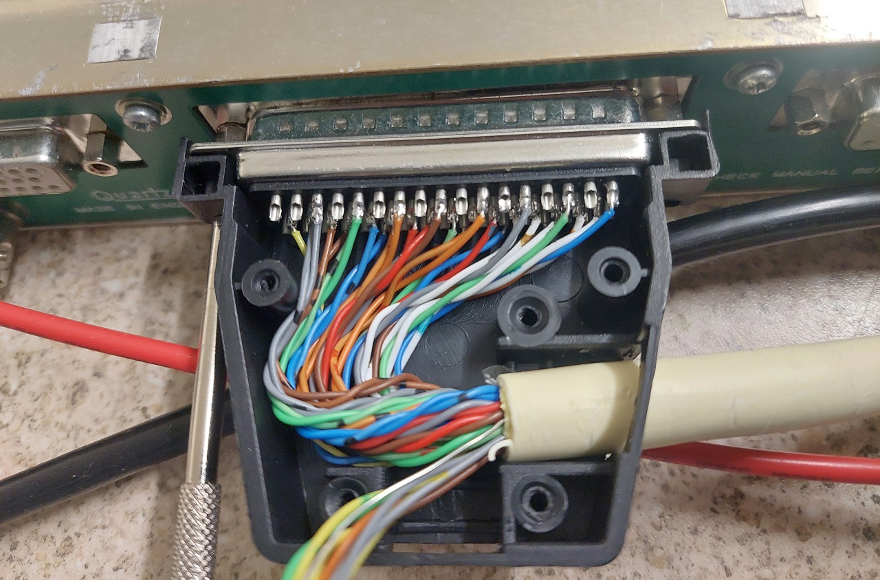
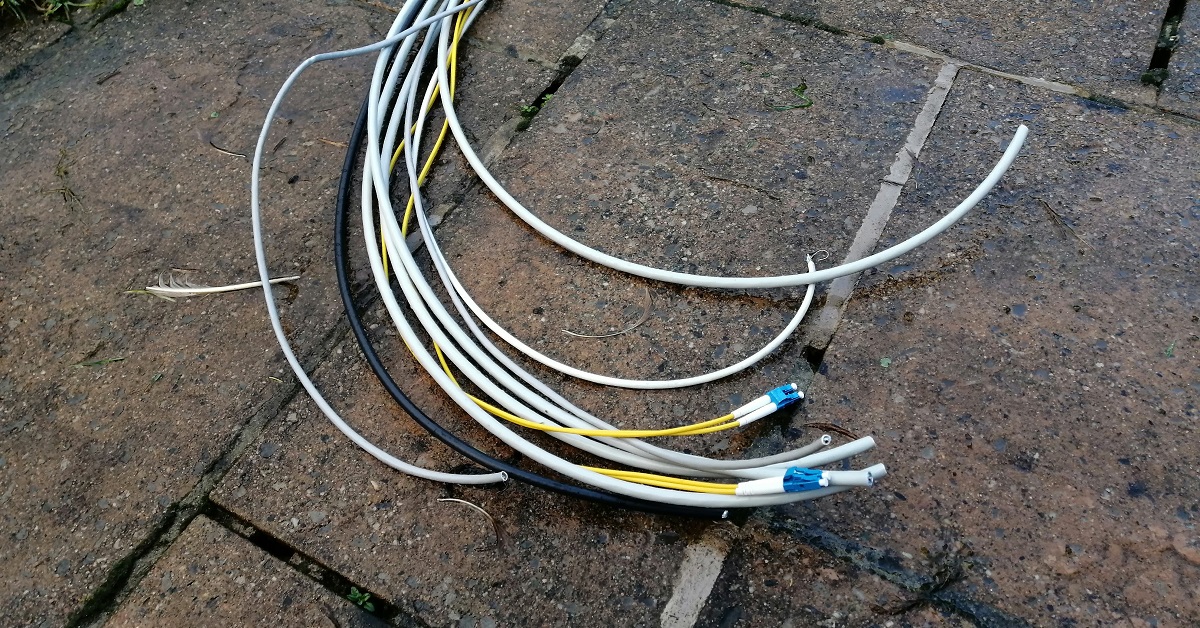
For this purpose, I bought an old 96 port patchbay ('jackfield' if you prefer) which I believe originally came from BBC Radio Ulster. First task was to completely disassemble it, remove all the cables and remove all the old solder, ready for me to add in my new cables. Actually wiring in all my connections was a very slow process. Each pair had to be cut to the right length and tied to the lacing bar, before being soldered into the connector.
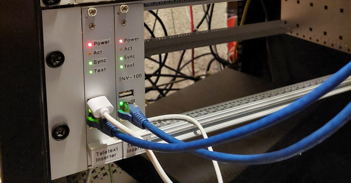
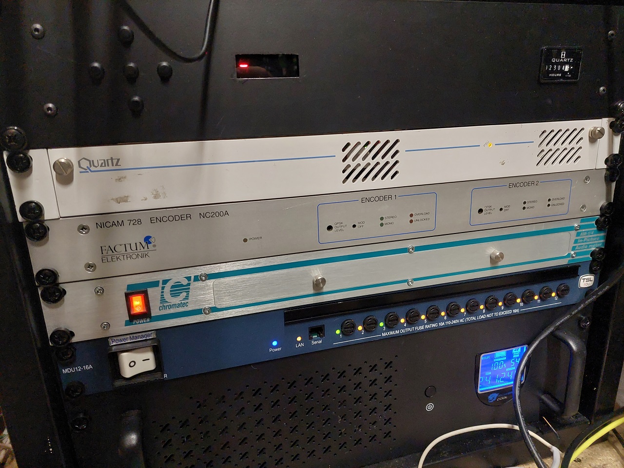
With all the connections wired up and tested, the next thing was to bring everything out to the attic, and get it all wired up into the rack! I haven't figured out exactly where the patchbay is going to live yet - it'll probably get it's own wall bracket behind the main rack to give easy cable access. But for now the matrix itself is in the rack, and controlling the audio to my 4 channel TV modulator.
- Nathan Dane, Dec 2023